
What Causes Oil Seals to Leak, and How Can You Prevent It?
Most oil seal leaks start in one of five places: a damaged or badly finished shaft surface, damage during installation, a rubber compound that does not suit the temperature or fluid, too much shaft runout or misalignment, or leakage around the outer diameter from a rough or damaged housing bore. Checking the failed seal and the shaft contact area usually shows which one.
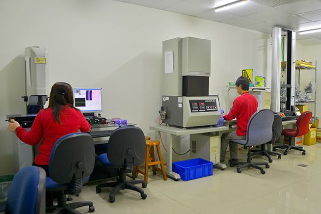
Leaks occur either at the inner diameter, between the lip and the shaft, or at the outer diameter, between the seal and the housing. When NIYOK designs and manufactures a seal, we check dimensions and lip friction at installation, choose materials carefully, and remind customers to replace seals near the end of their service life before the rubber ages and loses elasticity.
Cheap seals made from poor-quality compounds are a common cause of leaks and loosening, so it pays to work with an experienced seal manufacturer. NIYOK has worked in the original-equipment parts supply chains of Honda, Nissan and other carmakers in Taiwan, and has produced oil seals, gaskets and industrial parts for vehicle parts makers including Athena S.p.A., Vedamotors and Kuo Motor.
Q1. What are the most common causes of oil seal leakage?
Look at the failed seal and the shaft together: the wear pattern usually points to one of the causes below.
| What you see | Likely cause | What to check or change |
| Leak at the lip, with a polished groove worn into the shaft | Shaft surface too soft, or abrasive dirt reaching the lip | Shaft hardness (at least 45 HRC; 55 HRC or more for dirty or high-speed duty). Use a seal with a dust lip (T or K type) or a wear sleeve. |
| Leak right after installation; lip cut, nicked or folded | Lip damaged during assembly by sharp edges, keyways, splines or threads | Lead-in chamfer and rounded edges on the shaft; a mounting sleeve over keyways and threads; lubricate the lip before fitting. |
| Lip hard, glossy or cracked | Overheating from friction at high speed, dry running, or a compound used beyond its temperature limit | Lip temperature against the material limit and lubrication at the lip. Consider ACM or FKM. |
| Lip swollen and soft, or shrunk and hard | Rubber not compatible with the oil, fuel, coolant or additives | The actual fluid and its additives; choose a compatible compound. |
| Steady leak with no visible lip damage | Spiral machining marks on the shaft pumping fluid out, or a surface that is too rough or too smooth | A plunge-ground shaft with no spiral marks, Ra 0.2–0.8 µm and Rz 1–4 µm. |
| Wear on one side of the lip only | Shaft runout, or the seal sitting off-center or tilted in the bore | Shaft runout and bore concentricity; press the seal in square to the shaft. |
| Lip turned over or pushed out | Internal pressure higher than the seal is designed for | Standard rotary shaft seals are designed for about 0.05 MPa (0.5 bar) at most. Vent the housing or use a pressure-rated design. |
| Leak around the outer diameter | Housing bore damaged, too rough or out of tolerance, or the seal OD damaged when pressed in | Bore to ISO H8 with Ra 1.6–6.3 µm and a lead-in chamfer. A rubber-covered (C type) OD is more forgiving. |
Q2. What shaft and housing bore does an oil seal need?
Most leaks can be prevented at the design stage by getting the shaft and bore right. The values below are general recommendations for standard rubber rotary shaft seals, based on common ISO 6194 / DIN 3760 practice. High speeds, pressure or special media may need different values; our engineers can review your design.
| Feature | Shaft | Housing bore |
| Tolerance | ISO h11 | ISO H8 |
| Surface roughness | Ra 0.2–0.8 µm, Rz 1–4 µm, Rmax 6.3 µm or less | Ra 1.6–6.3 µm, Rz 10–20 µm |
| Hardness | At least 45 HRC; 55 HRC or more for high speeds or contaminated environments | — |
| Finish | Plunge ground, with no spiral machining marks, scratches, pores or burrs | Clean and burr-free |
| Lead-in | Chamfer or radius on the shaft end, with rounded, burr-free edges | Chamfer or rounded edge at the bore entry |
Q3. How do I install an oil seal correctly?
Keep the lip clean, lubricated and protected, and press the seal in straight.
1. Clean the shaft and bore and check them for burrs, scratches and old wear grooves. If the old seal wore a groove, use a wear sleeve or position the new lip on an unworn track.
2. Check the direction: the main lip (spring side) faces the fluid being sealed.
3. Lightly lubricate the lip with the fluid it will seal, or with grease. On seals with a dust lip, fill the space between the lips with grease.
4. Cover keyways, splines and threads with a mounting sleeve so they cannot cut the lip.
5. Press the seal in with a flat tool that pushes close to the outer edge, keeping it square to the shaft. Do not hammer the seal directly or let it tilt.
6. After installation, check that the seal is square and concentric and that the spring is still in place.
Q4. Can NIYOK help find out why a seal is leaking?
Yes. Send us the failed seal if possible, photos of the shaft contact area, and the operating conditions: fluid, temperature, pressure, shaft speed and how long the seal ran. Our engineers review the failure mode and recommend changes to the seal design, material or mating parts. For quality issues in production, we follow our 8D and CAPA process, with an initial response within 24 hours. Learn about our quality improvement process.
- Related Products
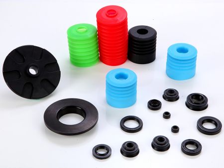
Shock Absorber Seal & Cover
NIYOK shock absorber seals and dust covers keep damping oil or gas inside the shock absorber...
Details